This article is a result of questions that are asked frequently by my students in vSAN classes. The subject of striping sounds very simple at first, but it turns out to be quite complex once you start going away from the simple standard examples. We shed light on the striping behavior of vSAN objects in mirroring, erasure coding, and for large objects. We also show the different striping behavior before vSAN 7 Update 1 and after.
What is striping?
Striping generally refers to a technique in which logically sequential data is segmented in such a way that successive segments are stored on different physical storage devices. Striping does not create redundancy. In fact, the opposite is true. In traditional storage, striping is also referred to as RAID 0 (note: RAID 0 -> zero redundancy). By distributing the segments over several devices that can be accessed in parallel, the overall data throughput is increased while latency is reduced.
Stripe size or stripe width is the number of segments an object is split into.
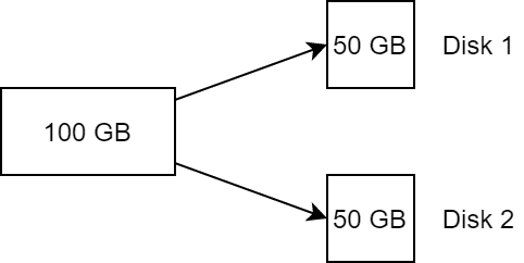
With a stripe width of 2, an object of 100 GB, for example, is split into two components of 50 GB each and distributed across two storage devices. This corresponds to a RAID 0.
SPBM and Striping
VMware vSAN offers the flexibility of storage policies that can be individually defined per object. It is not the datastore that determines the properties such as failure tolerance or stripe size, but the policy that is attached to the object. This is known as Storage Policy Based Management (SPBM).
Two key properties that can be defined by a vSAN storage policy are failures to tolerate (FTT) and stripe width (number of disk stripes per object). Failure Tolerance defines the number of copies of an object that must be distributed across independent fault domains. Stripe Width has nothing to do with fault tolerance, but is used to increase data throughput by distributing the objects as multiple components over multiple physical storage devices (disks).
The number of objects in the vSAN cluster is determined by the number of copies multiplied by the number of stripe segments. A 100 GB object with a policy of RAID1, FTT=1 and SW=2 consequently results in 2 objects with two components each (stripe segments).
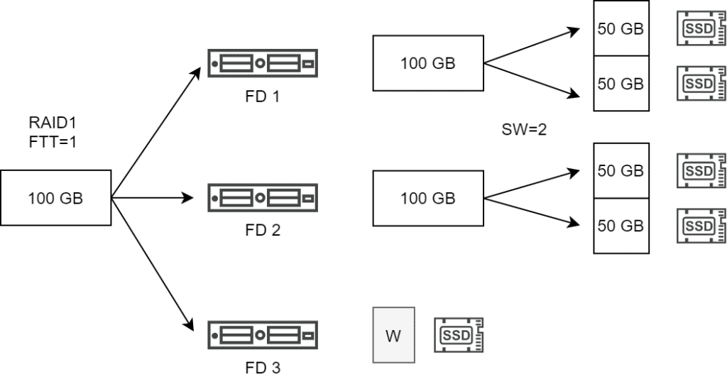
The vSAN host attempts to place the stripe components on different disk groups. If this is not possible, different disk devices are used within the same disk group.
What about Erasure Coding?
Erasure coding breaks down information into components and extends them with redundancy information using parity checksums. These are stored on physically different locations on a storage system.
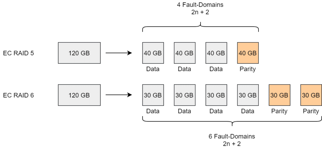
Erasure Coding (EC) is only available in All-Flash (AF) clusters. It can optionally be configured as RAID5 (FTT=1) or RAID6 (FTT=2). Four components are created for RAID5 and 6 components for RAID6 (see image below).
If we look at the stripe width (SW) in Erasure Coding, we have to distinguish the behavior before vSAN v7 Update1 and from vSAN v7 Update 1 on.
The past – Before vSAN7 U1
A 120 GB object with RAID5 and SW=4 has to be distributed over four fault domains (FD). Each of the objects was split into 4 components and located on different disks.
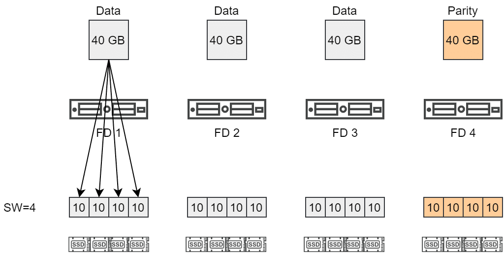
This behavior led to a heavy component split, although the RAID5 policy alone achieved striping over 4 components, which are also distributed over 4 fault domains as well.
The present – Since vSAN7 U1
With vSAN7 U1 this behavior changed. The stipe width now defines the minimum number of components. Erasure Coding RAID5 automatically distributes an object over 4 hosts (Fault Domains, FD). This means that the default SW of 1, 2, 3 or 4 is already fulfilled.

Only when a SW of greater than 4 is specified, further stripes are formed. This then applies for SW=5, 6, 7 or 8.
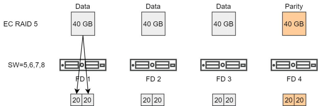
Stripes in Erasure Coding RAID5 policies must be specified in multiples of 4 to be effective. Similarly, the stripes for RAID6 must be specified in multiples of 6 to achieve an effective segmentation.
An object with an EC RAID6 policy and SW=12 would be distributed across 6 hosts, with 2 components per host (=FD). So a total of 12 components as opposed to 6×12 components before vSAN7 Update1.
Big Objects
Regardless of the selected stripe size, vSAN automatically splits objects larger than 255 GB into multiple components.

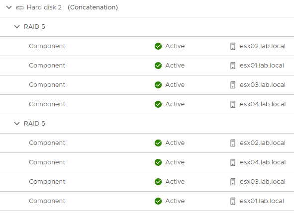
In the example above, a forced split of the object at 255 GB into two components occurs. The components will be distributed as RAID5 over four fault domains (here hosts). A Stripe Width of 1, 2, 3 or 4 produces the same result again.
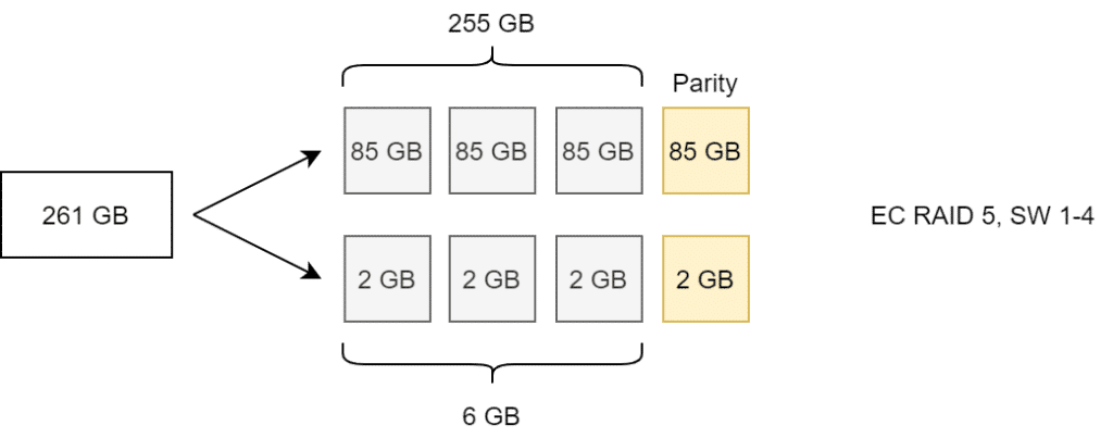
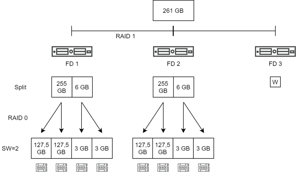
Only at SW=5 the number of components doubles. (Example with 261 GB for better calculation)
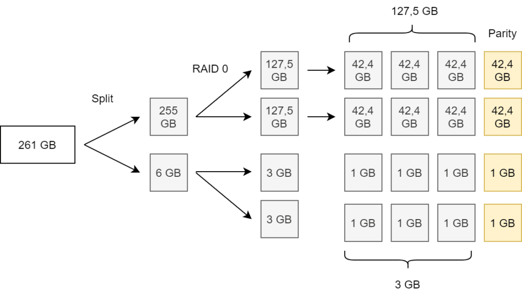
Note that splitting large objects is an asymmetric split (255 GB plus 6 GB), while striping will result in symmetric component split (see illustration above).
Mirror Policy and large Objects
When using a Mirror Policy (RAID 1) with objects larger than 255 GB and a stripe width of 2, the result is as illustrated below. First, the mandatory split of the large object is applied, followed by striping (RAID 0). A RAID 1 is formed over all components to create redundancy over several fault domains (here 2 hosts plus witness).
Tracking the Objects
In vSphere Client, we can select the VM and then go to Monitor > Physical Disk Placement to see the component layout. However, we do not get any information about the size of the components. Here esxcli is helpful.
esxcli vsan debug object list
This command returns all cluster objects with details like object UUID, owner, size, policy, allocation, or votes. This can quickly become very confusing. It is best to redirect the output to a file.
esxcli vsan debug object list > /tmp/objects
The generated text file can be downloaded from the ESX host to a Windows workstation via SCP, then be browsed with an editor of choice (e.g. Notepad++).
Note the different path separators in ESXi and Windows.
scp root@esx01.lab.local:/tmp/objects c:\temp\objects
The screenshot below shows an excerpt from the object list. The object (vDisk) has a size of 260 GB. It will be split into chunks of 255 GB and 5 GB. According to RAID5 policy this will result in 3×85 GB = 255 GB for data plus 85 GB for parity and 3×1.67 GB = 5 GB for data plus 1.67 GB for parity (see red box).
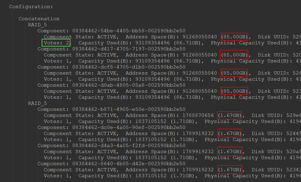
A side note is worth mentioning here. One of the components has two votes (green box). This is always the case with Erasure Coding policies, as the sum of all votes must not be an even number, since quorum always requires more than 50% of all votes. Actually, Erasure Coding cannot lead to a split-brain scenario. In contrast to RAID1, we do not have complete copies, only sub-segments. A 2+2 split results in an incomplete and thus unreachable object for both sides. Nevertheless, one of the objects gets 2 votes to guarantee an odd number. It’s the law! 😉

Hi:
Thanks for the nicely written article. I would like to seek your expert opinion with regards to this technology. In my environment we have 2 vsan clusters, but right now we’re in a juncture to continue with vsan or to procure an external storage due to the increase in VMware pricing.
I would like to understand more regarding vsan’s behavior for FTT=1 as I had rather negative experience with it. I tried to search and also read up on VMware’s article/blog post/videos but wasn’t able to find a good explanation on whether vsan is a Raid 1+0 or Raid 0+1 when FTT is set to 1. I understand that when an object is smaller than 255GB then it’s just Raid 1. But if I have a disk group of 7 capacity disks, and the object is sliced into 7 pieces, do I get raid 1+0 or 0+1?
The reason I ask is because I personally saw, on a quiet system, when I pulled out 1 capacity disk and reinserted the disk to force a reconstruction, all the disks in the disk group were blinking constantly until the reconstruction is completed. This is more like a raid 0+1 behavior. I need
Continue:
I need a better explanation to this behavior. Probably a vmware document or some expert explanation is the best.
Many thanks.
regards,
Bong